

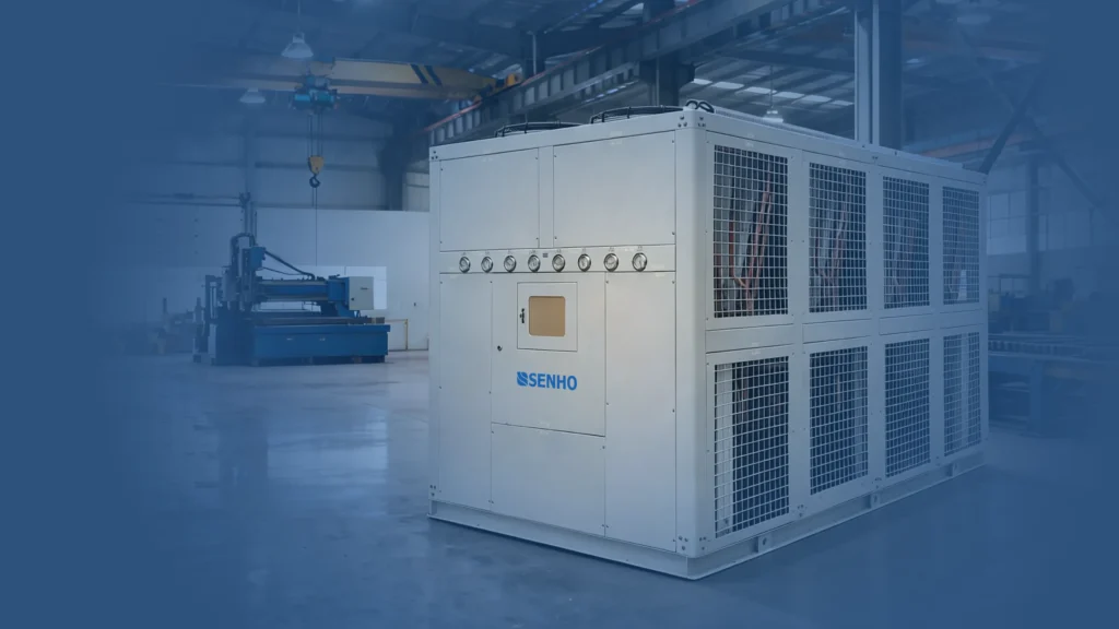
The primary purpose of an industrial chiller is to neutralize the heat load generated by your production process, ensuring your equipment and materials remain within a precise, required temperature range.
Therefore, the foundational step in sizing a chiller is accurately determining the heat load of your specific operation. However, calculating the cooling capacity is only the beginning. To guarantee the chiller is perfectly suited for your facility, several secondary factors must be evaluated—such as cooling methods (air vs. water), circuit types (open vs. closed), and site-specific pump requirements.
As a dedicated chiller manufacturer and cooling solution provider, this guide is designed by our engineers to walk you through the essential steps of sizing an industrial chiller.
Phase I: Calculating Required Cooling Capacity (Heat Load)
At the core of thermal energy, heat load can always be calculated using the fundamental thermodynamic formula:
$$Q = c \cdot m \cdot \Delta t$$
- $Q$: Heat load (Cooling Capacity)
- $c$: Specific heat capacity of the material being cooled
- $m$: Mass (weight) of the material
- $\Delta t$: Temperature difference (Target Temperature vs. Initial Temperature)
While this formula is mathematically precise, sourcing the exact variables for every application can be challenging. To make sizing more convenient, our engineers have developed simplified, industry-specific formulas based on decades of practical experience.
(Note: The following calculations are standard industry references. A 1.5x safety factor is highly recommended and integrated into these formulas to account for environmental fluctuations and heat loss.)
1. Plastics & Rubber Industry
A. Extrusion, Blow Molding, and Film Blowing
For standard plastic processing, the specific heat of most plastics is typically below $0.55 \text{ Kcal/(kg} \cdot ^\circ\text{C)}$, and the process temperature difference rarely exceeds 200°C. Incorporating a 1.5x safety factor, we can simplify the thermodynamic formula to:
$$Q (\text{Kcal/h}) = \text{Productivity} (\text{Kg/h}) \cdot 165$$
B. Injection Molding (Excluding PET Preforms)
The volume of plastic an injection molding machine processes is directly tied to its clamping force, which dictates the heat load. Because molds and materials change frequently, chiller sizing must ensure adequate capacity for the highest possible demand.
As a general rule, 80 Tons of clamping force requires 2150 Kcal/h of cooling capacity.
$$Q = \frac{\text{Clamping Force (Ton)}}{80} \cdot 2150 \text{ Kcal/h}$$
Example: For a 1000-Ton injection molding machine:
$$Q = \frac{1000}{80} \cdot 2150 = 26,875 \text{ Kcal/h}$$
C. PET Preform Manufacturing
PET preform manufacturing is unique because it strictly processes one type of material, allowing for highly accurate thermodynamic calculations based on productivity.
Step 1: Calculate Productivity ($m$)
Determine the number of cavities, the weight per preform, and the cycle time.
Example: 32 cavities, 60g per preform, 5-second cycle time.
- $m = 60\text{g} \cdot 32 \cdot (\frac{3600\text{s}}{5\text{s}}) = 1,382,400\text{g/h} = 1384.2 \text{ kg/h}$
Step 2: Calculate Heat Load ($Q$)
Assume the molten PET enters the mold at 260°C and must be cooled to 15°C ($\Delta t = 245^\circ\text{C}$). The specific heat of PET is $0.53 \text{ Kcal/(kg} \cdot ^\circ\text{C)}$.
$$Q = c \cdot m \cdot \Delta t \cdot 1.5$$
$$Q = 0.53 \cdot 1384.2 \cdot (260 – 15) \cdot 1.5 = 269,607 \text{ Kcal/h}$$
2. Universal Calculation for Other Industries
If your industry is not listed above, you can calculate the heat load by measuring the cooling water itself, rather than the product.
- Step 1: Determine the Flow Rate ($m$) – Check your equipment’s manual for the required cooling water flow rate, or measure it directly using a flowmeter.
- Step 2: Determine the Temperature Difference ($\Delta t$) – Use an infrared thermometer to measure the water temperature at the inlet and the outlet of your equipment. Subtract the inlet temp from the outlet temp.
- Step 3: Calculate – Using the specific heat of water ($4.187 \text{ Kj/kg} \cdot ^\circ\text{C}$), apply the formula.
Example: A flow rate of $5 \text{ m}^3\text{/h}$ ($5000 \text{ kg/h}$) and a $\Delta t$ of 4°C:
$$Q = 4.187 \cdot 5000 \cdot 4 \cdot 1.5 = 125,610 \text{ Kj/h}$$
(Note: $1 \text{ Kcal} \approx 4.184 \text{ Kj}$)
Phase II: Selecting the Right Chiller Configuration
Once the cooling capacity is determined, the physical configuration of the chiller must be matched to your facility’s infrastructure.
1. Air-Cooled vs. Water-Cooled Chillers
- Air-Cooled Chillers: Best suited for well-ventilated, open, or drafty areas. They do not require a cooling tower, making them ideal for facilities where water is scarce or expensive.
- Water-Cooled Chillers: Highly efficient and quieter, making them the standard choice for indoor installations. However, they require access to a dedicated cooling tower and a maintenance team to periodically clean the condenser tubes to prevent scale buildup and efficiency drops.
2. Open Circuit vs. Closed Circuit Systems
This refers to the chiller’s internal pumping system, not your entire facility’s plumbing.
- Closed Circuit Chillers: Required if you already have an external, open reservoir (like a large concrete cooling pool) or if your equipment features an open water sink (e.g., pipe extrusion immersion baths). The chiller operates as a closed loop pulling from these open sources.
- Open Circuit Chillers: Features a built-in water tank. This is ideal if your processing equipment has a closed-loop water channel and no external reservoir is present.
Phase III: Advanced Customization Requirements
To ensure operational longevity, always communicate specific process parameters to your chiller manufacturer:
- Non-Corrosive Water Circuits: Industries such as laser cutting, food and beverage, or electronics often require deionized (DI) or reverse osmosis (RO) water. Other sectors, like electroplating, deal with highly corrosive fluids. In these cases, the chiller’s internal piping and evaporators must be upgraded to stainless steel or titanium to prevent degradation.
- High Water Pressure Demands: If there is a significant physical distance—especially vertical elevation—between the chiller and your processing equipment, standard water pumps will fail to deliver adequate flow. High-lift or high-pressure custom pumps must be integrated into the unit’s design.
In Summary: Thoroughly analyzing your working conditions prior to purchasing an industrial chiller is critical. A correctly sized and configured unit will streamline your production process, eliminate overheating bottlenecks, and ultimately maximize your operational profitability.